
Built-in vs Detachable NFC Antennas: A Kiosk Integration Checklist
Choose antenna placement around the finished device, then test the intended cards in the assembled enclosure.
OEM procurement guide
A compact reader board and a detachable antenna solve different layout problems. For a kiosk or embedded device, the useful comparison includes the card presentation area, mounting space, antenna position, interconnection and the conditions under which the application must read cards.
Start with the integration requirement
ACM1552U-Z2 has an integrated antenna on a compact board. ACM1552U-Y3 uses a separate detachable antenna board. A detachable layout offers a different placement option; it does not, by itself, establish a longer reading distance or better performance inside your enclosure.
Ask for selection support1. Define where the user presents the card
Mark the intended card presentation area on the equipment drawing. The reader should be evaluated in the location and orientation that users will actually use.
- Identify the card or tag model, intended orientation and required read/write operation.
- Record the enclosure surface between the antenna and card. Include the expected user positioning in the test plan.
2. Compare the complete mounting layout
For Z2, the board and antenna share the compact assembly. For Y3, plan space for both the reader board and the detachable antenna board, together with their interconnection.
- Check mounting points, connector access, cable routing and clearance in the finished device.
- Request the supported antenna assembly and cable details. Do not assume a different antenna or longer cable is compatible.
3. Request the mechanical drawing for the supplied revision
Use the current drawing to check the proposed assembly before committing to enclosure tooling. Y3 dimensions differ between manufacturer documents, so a copied dimension is not sufficient for a purchase drawing.
- Identify the hardware revision and confirm the reader board, antenna board and interconnection drawing.
- Allow for connectors and cables as well as board dimensions. Confirm the assembled scope in the quotation.
4. Test in the enclosure, with surrounding equipment present
A bench result is one test condition. The equipment enclosure, antenna surroundings and active electronics belong in the evaluation of the finished assembly.
- Test the intended cards in the installed position, with the equipment assembled and its relevant electronics operating.
- Record antenna placement, nearby materials, cable assembly, card orientation and the application outcome. Use those conditions when comparing changes.
5. Keep a repeatable evaluation record
Choose acceptance criteria for the application's real task. Measure results under named conditions rather than treating a manufacturer's maximum distance as a guaranteed installation result.
- Record the module revision, firmware, host/software, card sample and exact operation tested.
- Use a recorded number of repeated trials at the intended positions. Note successful operations, errors and reconnect behaviour; repeat the same method after a layout change.
6. Confirm what the quoted assembly includes
The purchase brief should distinguish the module, antenna assembly, cables and security or development items. An optional feature is not evidence that it is included in every unit.
- For Y3, confirm whether the optional Class A (5 V) SAM slot is included, and whether a separate SAM card is needed.
- List evaluation and expected order quantities, delivery country and schedule. Confirm the approved assembly, sample availability, MOQ and lead time in the quotation.
Models to investigate
-
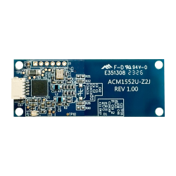
ACM1552U-Z2
A compact module with an integrated antenna for layouts that keep the reader board near the card presentation area.
Confirm before ordering: Evaluate board position, mounting, cable clearance and the intended cards in the actual enclosure.
-
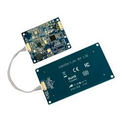
ACM1552U-Y3
Separate reader and detachable antenna boards provide a different placement option.
Confirm before ordering: Confirm the supplied revision, current mechanical drawing, antenna interconnection and optional SAM scope before ordering.
What to include in your enquiry
- Enclosure drawing and intended card presentation area
- Card or tag samples, required operations and host software
- Reader and antenna mounting, nearby materials and cable routing
- Required boards, cables, SAM and evaluation assembly
- Recorded test conditions, evaluation quantity, destination and schedule
Discuss your OEM NFC integration
Share your host, cards, enclosure and evaluation needs so the enquiry can address the right module and configuration.
Ask for selection supportPrice, sample availability, MOQ and lead time require confirmation in the quotation.
Frequently asked questions
Does a detachable antenna always read farther?
No installation result follows from that layout alone. Compare the actual assemblies with the intended card, placement, enclosure and application operation under the same recorded test conditions.
Can I replace the Y3 antenna or extend its cable?
Request the supported antenna and interconnection specifications for the exact configuration. Do not assume an arbitrary antenna or cable extension is supported; evaluate any approved change in the finished assembly.
Are a SAM slot and a SAM card the same purchase item?
They are different items. Y3 lists an optional Class A (5 V) SAM slot. Confirm whether the slot is included and whether the project requires a separate SAM card or development kit.
Manufacturer references
The links below support model-specific facts. The evaluation steps are a project planning checklist; confirm the supplied hardware, firmware and accessories.